 MEMBERSHIP LOGIN
 JOIN PRI
Ask the Experts: The Do’s and Dont's of Crankshaft Balancing
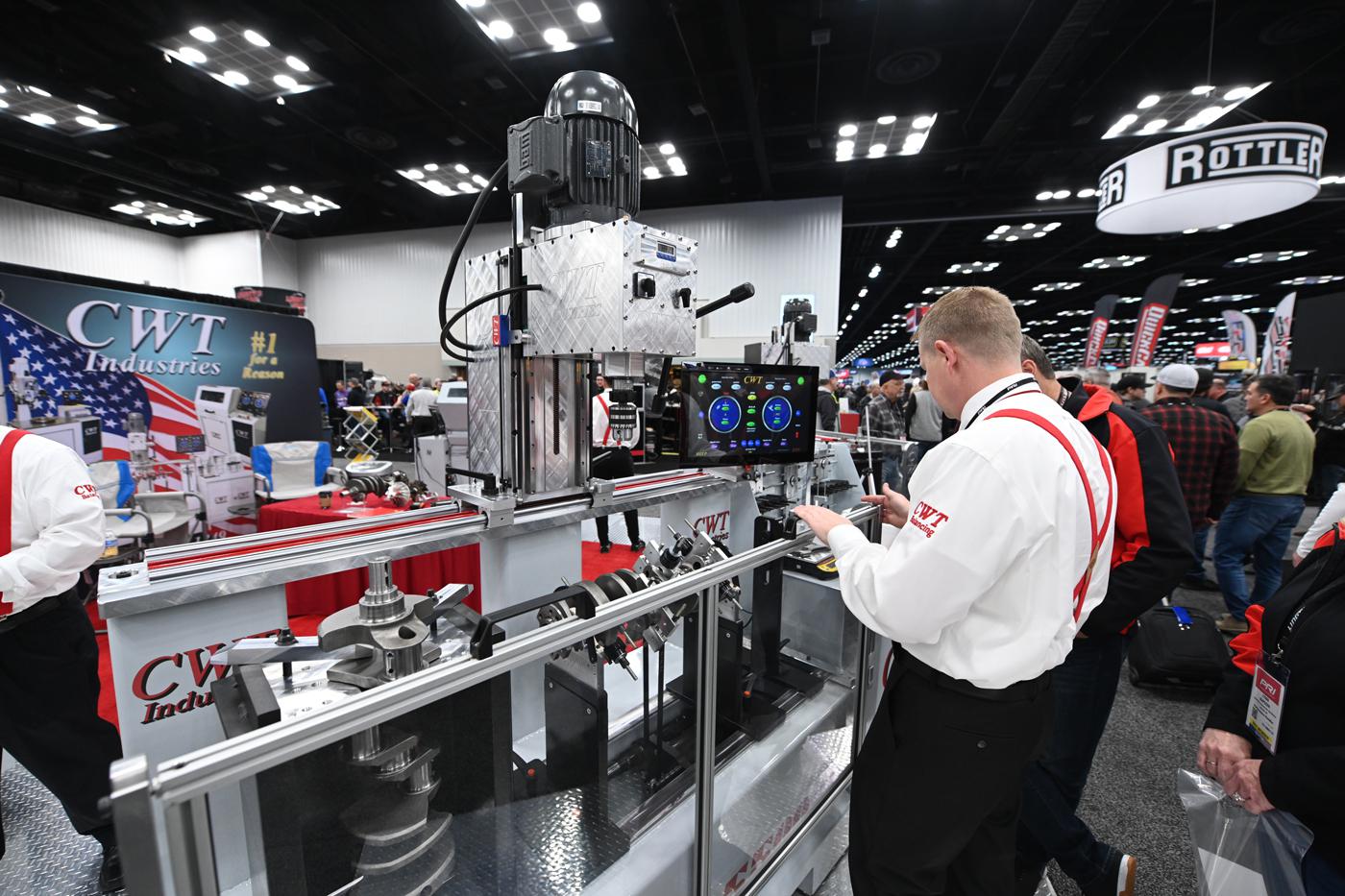
Procedure is key to proper crankshaft balancing, said CWT Industries’ Randy Neal. Here, CWT demonstrates a crankshaft balancing machine at the PRI Show.
Balancing engine components is an exact science, and small mistakes can have a big impact on accuracy.
Maximizing the efficiency of an engine is the key to unlocking all of its performance potential, and crankshaft balancing has played an important role in that effort for some time now. But while balancing tools have become more sophisticated over the years, they’ve also introduced opportunities for more mistakes that can negatively affect the end result.
“Everything is procedure,” said Randy Neal of CWT Industries, Norcross, Georgia. “If you can’t properly measure, you can’t properly determine value. Balancing is really a matter of getting everything established in a proper process.”
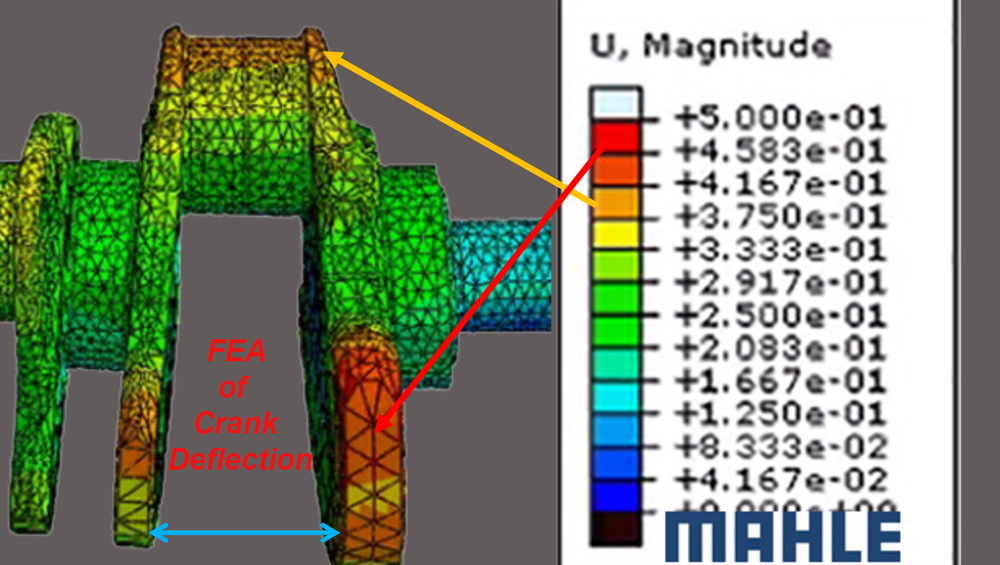
Akhil Nath of ABRO Balancing in Murfreesboro, Tennessee, noted that part of that procedure involves adhering to ISO balancing standards in much the same way that OEMs do. “The best way to balance is to use a low-speed machine that spins the crankshaft at about 200 to 300 rpm,” Nath explained. “If you spin a long shaft—especially those diesel ones—at a higher speed of, say, 1,000 or 1,500 rpm, it won’t be properly supported on the balancer, and that will change the readings. Inside the engine the crankshaft is supported on various bearings. But on the balancer, you’re using only two end supports, and if you run it at a higher speed, it can cause the shaft to bend and deform because it lacks support in the center. If that happens, it’s going to give you inaccurate readings. Unbalance shouldn’t change with speed because the crankshaft isn’t supposed to deform. There’s really no benefit to running it at higher speeds.”
Neal also pointed to the process of correcting the crank as another area where mistakes are commonly made. “We’re at a stage where we’re making so much power now that the counterweights are distorting and becoming ‘hostile.’ The counterweight is meant to develop a mass of weight that offsets the piston rod assembly mass, but it has to be stable when it’s running. If you are going to drill, we tell people it should be no more than two holes that are a half-inch deep. Any time you go past that, you run the risk of making the counterweight go out of control. If you have to take out more than, say, 50 grams, you’re probably going to get out of the scope of normal drill depth. We have software on our machines that will show you how you can put the crank in a lathe and cut down the counterweight—in other words, reduce the radius of it—instead. That way the counterweight maintains its structure, and it lowers the polar moment of energy as well as the moment of inertia.”
Nath said that another frequent mistake can create inaccurate measurements right out of the gate as well. “You’re using a belt drive to drive the crankshaft—great,” he said. “But on one side of the belt drive people have a habit of sticking on some kind of magnet that is running the encoder to get the angle on their software. When you do that, you’re actually adding an error on one side of the crank because you’re not compensating for that weight. That magnet isn’t going to be there when the crankshaft is running in the engine, so if you do this, you’re never going to properly balance the crankshaft for the environment that it’s going to be used in.”
To address this, Nath suggested either compensating for that additional weight or using an encoder inside the driving motor of the balancing machine instead. “The most accurate way to compensate is within the software, but using an encoder inside the driving motor is really the best option because then there’s no attachment involved.”
He also said that people often inadvertently cause damage to either the balancing machine rollers or the crankshaft’s rod journals when drilling counterweights due to the pressure of the drill.
“Over time you’re either going to damage the machine, or you’re going to consistently damage the journals of the crankshaft,” Nath explained. “You need to have anti-thrust compensation—essentially a mechanism that lifts the crankshaft so it isn’t resting on the rollers. Once you lift it, you can’t damage the journals or the rollers of the machine.”
Neal added that many of these issues have been allowed to perpetuate because racers and engine builders have a tendency to falsely associate the results with on-track competitiveness.
“For example, I tell people to be careful about getting away from 50% unbalance on the bob weight formula. Some people want to go over, some people want to go under—I’ve been listening to this for years and years. There are plenty of good engine builders who have their beliefs, but I’m coming at it from the engineering side of this. Give me the data, and I’ll support you. That’s where folks tend to get lost. They might say, ‘Well, I’m winning races, that’s how we figured this out.’ That doesn’t count. Everything is math; there’s no getting around it.”
SOURCES
ABRO Balancing
abrobalancing.com
CWT Industries
cwtindustries.com