 MEMBERSHIP LOGIN
 JOIN PRI
Happy Days
With cam designers constantly pushing the limits, valvetrain engineers have stepped up their game to keep engines content.
Keeping the valve springs “happy” is an excellent summation of the direction that camshaft and valvetrain development has taken over the past decade. Valvetrain failures used to dominate conversations in garages and engine shops, but those grumbles have slowly been silenced by a number of factors, including better materials, extensive testing and improved manufacturing processes.
“We’ve never stopped working on parts,” said John Partridge of Bullet Racing Cams, Olive Branch, Mississippi. “Of course, we’re always looking for power, and valvetrain control is the biggest issue.”
The valvetrain has been drawing more attention in recent years, even though the camshaft is the drum major that directs the marching band of valvetrain components.
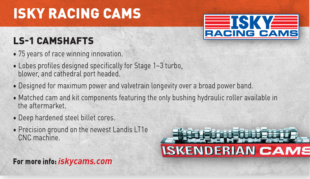
“It’s the entire combination,” added Nolan Jamora of Isky Racing Cams, Gardena, California. “More people have dynos, and we get really good feedback and know the range where they want to dial in a little bit more.”
“But the cam guys are always pushing the limits,” noted Trip Manley of Manley Performance Products, Lakewood, New Jersey.
No Camshaft Too Big
Camshaft manufacturers are able to push those limits to unexpected extremes because of improvements in lifter design, pushrod stiffness, valve-spring durability and lighter but stronger valves. They’re also beefing up camshaft construction with tougher steel materials to reduce camshaft twisting and bending that interferes with the optimum timing of valve events or creates unwanted harmonics in the system.
“A lot of guys are upgrading their camshaft materials, even in classes like Top Sportsman and Top Dragster,” said Guy Aguayo of Crower Cams & Equipment Company, San Diego, California. “They’re going from 8620 steel billet to 9310 cores. It seems like there’s no such thing as a camshaft that’s too big. Guys are going over 1-inch valve lift on a regular basis. They’re getting to just under what a Pro Stock engine would use.”
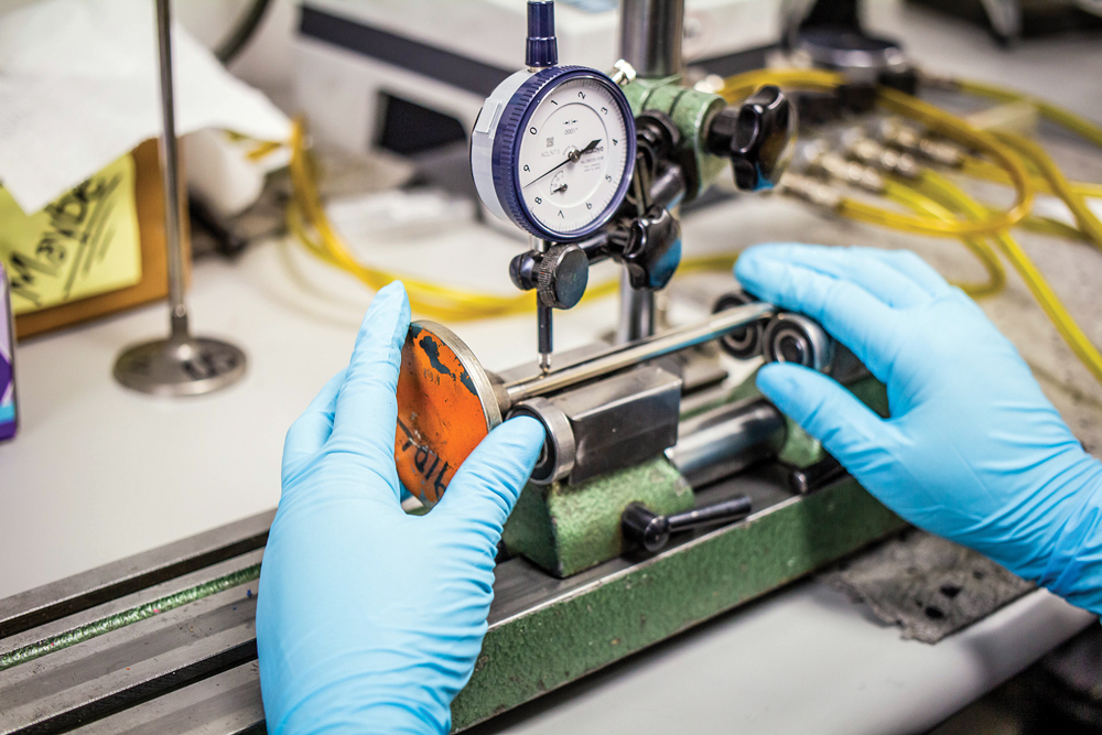
Callies Performance Products in Fostoria, Ohio, has seen this trend in upgrading cam cores as it offers two popular types to the industry, including tool steel and induction-hardened, or carburized, 8620 steel.
“Tool steel is in a class of its own,” said Brook Piper. “But a lot of guys like the induction-hardening because that’s what the OEMs do. It’s less expensive and good for a variety of applications. So, it all depends on what they like.”
The Callies cores are rough machined to the proper bearing size and lobe pattern before race shops and cam companies finish grind to the exact specs. Piper said the company is slowly starting to finish-grind more cams for a wider customer base. Most of the current finish-grinds are for users who need a high number of similar cams at once, such as a Top Fuel team.
So much attention is paid to camshafts these days because it is a significant part of the engine’s overall power potential, and it’s a hardware component that can easily be changed and tested. Very few engine builders will change piston design, intake-manifold dimensions or cylinder-head porting without having first tested a variety of cams.
“Everyone is looking for an edge. Three or four horsepower used to be a butt whooping in Cup racing. Now it can be a butt whooping at the Chili Bowl or something like that,” added Chris Straub of Straub Technologies, Piney Flats, Tennessee. “I tell them that cylinder pressure creates torque at the end of the day. Torque and rpm create horsepower.”
Ironically, one of the keys to gaining a small valvetrain edge lies in the cylinder block. Straub recalled an engine builder telling him that a Straub camshaft was off by six degrees when installed, even though the cam had checked out perfect on a Cam Doctor. Straub asked about the block and discovered it was one that had a reputation for inaccurate lifter-bore positions.
“Long story short, one intake valve out of eight was correct on the camshaft lobe because the lifter angle was correct in the block. The other seven were wrong, and they varied from as much as four degrees advanced to three degrees retarded,” said Straub. “Correcting the lifter-bore angles can mean 30 horsepower. That’s a big difference.”
Engine builders are taking advantage of the latest CNC technology to ensure accurate lifter-bore angles and positions. They’re also increasing the lifter-bore diameter to support roller lifters with larger wheels, which in turn allow more aggressive lobe profiles. But those new lobe profiles can also be hostile to the valve spring on the opening cycle.
“If we can keep the spring from going into flux, we can do a lot more on the closing side,” explained Partridge. “Basically, it’s a design thing where we’re tweaking how aggressive we get at low lift and how much we move it in the middle to keep the spring from getting excited. If we can keep the spring happy, we’ll make more power. As soon as that spring gets unhappy, it’s going to lose power.”
“It’s tough to figure out the ramp speed with bigger cams. Sometimes the ramp speed can be a bit slower with cams that have a large base circle,” said Aguayo, noting that these discussions generally cover big-displacement drag racing engines. For circle-track racers, the strategy often focuses on not allowing the engines to overpower the track. “If they can keep from spinning the tire out of the corners, that’s ideal. For some drivers, the camshaft and engines are so aggressive that they keep spinning the tire. We need to tone them down a little bit. But the big sprint-car engines, they still use a big camshaft.”
Custom Camshafts
Tailoring camshafts to specific events, tracks and drivers basically means that most racing cams are custom made for engine builders. That process requires an enormous amount of information.
“Sometimes, people are a little surprised by the questions when they call our tech line,” said Billy Godbold of COMP Cams, Memphis, Tennessee. “Clearly, we will want to know about the engine, but they wonder why so many questions about the vehicle, track and driver specifics?”
Godbold described a detailed process, noting that the information required goes well beyond physical dimensions (including rod-to-stroke ratio), understanding all the airflow characteristics (both intake and exhaust), compression ratio and fuel type. In fact, even piston design has a strong influence on cam choice and will be considered by the tech reps.
“Perhaps the most important thing we will then ask about has to do with piston-to-valve clearance,” said Godbold. “Many engine builders can accommodate large valve reliefs, but these will often greatly reduce combustion efficiency. With an unrestricted engine that has great headers and a well-tuned intake, the engine may well want as much overlap as you can throw its way for maximum airflow and filling [the cylinder]. But the big reliefs required can hurt combustion efficiency, more than offsetting our potential gain in flow. Understanding these factors is hugely important.”
The application basics are then covered in full detail. “We always ask about rpm, but in general it is difficult for more engine builders to focus on where the vehicle performance matters the most,” said Godbold. “These types of considerations are often even more important in circle-track racing. Races can be won or lost on restarts, so we often ask multiple questions about the competition. Knowing where we are going to focus will greatly change how we set the exhaust opening and intake closing, and perhaps even the overlap we select. Every form of racing has very similar needs, which all require attention to ‘torque curve shaping.’”
Once these factors have been established, driver styles will be considered (see sidebar on page 98) to help determine the camshaft’s general specs. Finally, there are valvetrain limits and durability targets to consider. Key details include valve weight and pushrod/rocker-arm stiffness.
“We sometimes have the customer check his lift with full open load versus just checking a valve spring to calculate system stiffness, especially in combinations that are very well developed,” said Godbold, adding that the number of engine cycles are then considered. “It would blow your mind to compare the cycles on a NHRA Top Fuel run versus something like a five-mile Bonneville pass. Circle track and events like Drag Week move that decimal place over several more places.”
Critical Element
After all those calculations, the valve spring is the last critical element to be considered (see sidebar on page 104).
“Knowing the rocker ratio, general installed height and coil bind height, our technicians will be sure not to leave way too much or too little room at max lift,” added Godbold. “Finding the right combination requires a full systems approach.”
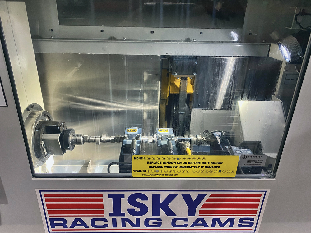
Working directly with engine builders who have dyno facilities and strong testing programs prompted Isky to purchase a new cam grinder to help reduce turnaround times for custom camshafts.
“We can come up with the grind specs, send them over and grind the cam in about 30 minutes,” said Jamora. “An engine builder could call up and tell us to add a couple degrees duration and put in three degrees of advance—we can do it that quick.”
Key to the program’s success is having enough cores in stock and having enough notice to finish the grind before the last shipping service pickup. Isky has also refined its popular bushed-lifter program by narrowing the choice of materials for the bushings to just two. Also, oiling strategy has been modified to increase durability, and the line has expanded to hydraulic rollers in many popular engines.

“We do lifters for Harley-Davidsons now,” added Jamora. “That’s how well the bushed lifters have spread to different applications.”
For open or unrestricted engines, cam suppliers have considerable flexibility. Some classes of racing, however, have limits on cam design, such as restricting the amount of total valve lift or requiring a minimum vacuum to control aggressive lobe overlaps.
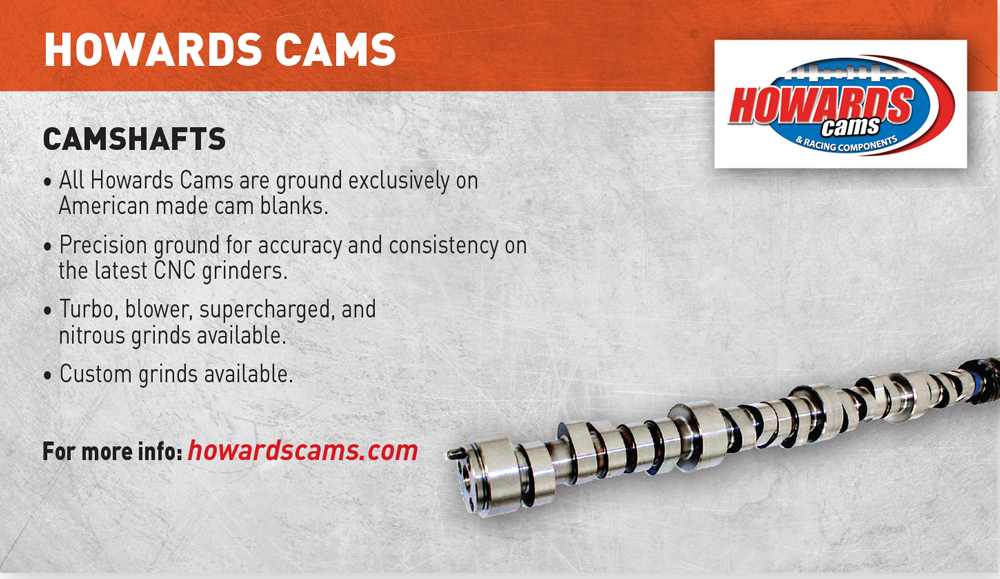
“With some guys, we have to wrap their heads around the fact that we’re not making the best cam for the motor. We’re making the best cam for the rules,” noted Eric Bolander of Howards Cams, Oshkosh, Wisconsin. “Sometimes it’s just a matter of getting good feedback from the customer about what the car is really doing and where the driver actually wants his power. Engines make about 3,500 rpm of good power, and that has to come from somewhere.”
Bolander recalled a customer who complained that his car was “lazy” at the drag strip, and he wanted a new camshaft that provided more torque.
“He calls back to tell me that he launched the car, put it on its back bumper and tweaked the quarter panels,” said Bolander. “He thought I was responsible because I gave him a cam with so much more torque. I said I am just the cam guy, not the driving instructor.”
Advanced Computer Simulation
Camshaft designers have generally relied on experience and a few math formulas when determining the specs for a customer. However, advanced computer simulation software now assists that operation at some shops. For example, Bullet Racing Cams is using a very sophisticated modeling program developed in Europe that has proven to be quite accurate.
“We took that information and ran it on a Spintron to see if it was accurate, and it was,” said Partridge. “We can take into account a lot of things, such as valve and rocker weights, spring rates, contact points. It’s really a lot simpler than running on a Spintron. We found it tells us more than the Spintron does.”
What Bullet is looking for goes back to keeping the valve springs happy. Partridge can make incremental changes in lobe design to see how they affect the entire valvetrain. The more information that the engine builder can provide to feed the computer program, the more accurate the engine model will be. Since Bullet works mostly with drag racing and circle-track teams, the research is more focused.
“We’re too small to be everything to everybody,” said Partridge. “It all trickles down. A guy with a high-end bracket car wants his stuff to be just as happy as the guy with a Pro Stock motor. We try to pass on the technology.”
Most recently, Bullet has been studying boosted applications and learning how to leverage lobe-design strategies developed for naturally aspirated engines.
“It all goes back to keeping the valve spring happy,” said Partridge. “We were able to take engines running at 10,500 and get them to 11,200 rpm just by doing some tweaking. We’ve focused a lot on supercharged engines because that’s a big part of the market for us.”
While software keeps Bullet moving forward, extensive dyno testing is helping Cam Motion in Baton Rouge, Louisiana, develop new cam strategies. One connection sometimes overlooked by engine builders is the relationship between the cam and the intake manifold runner lengths. The company recently conducted exhaustive dyno tests with a 6.0-liter LS engine equipped with stock 706 cathedral-port cylinder heads. Tests compared the factory intake manifold with 11-inch runners against an Edelbrock Super Victor with a carburetor and sporting runners about 6 inches long. Standard 1 7/8-inch diameter tubular headers were used for all tests.
Junkyard Dog and Titan King cams were tested, and both had similar lift numbers and exhaust duration. The only difference was that Titan King closed the intake valve four degrees later than the Junkyard Dog version.
“The long runner plastic intake appreciated the later intake valve close event much sooner than the shorter runner Super Vic intake,” explained Steven Balusik. “The 47-degree IVC (intake valve close) camshaft did not surpass the 43-degree IVC cam until 6,500 rpm when used with the short-runner Super Vic. Whereas the later 47-degree IVC camshaft caught up to the earlier 43-degree IVC cam at 5,100 rpm when using the long-runner OEM plastic truck intake. The shorter runner intake had more power under the curve with an earlier intake valve close event.”
Cam Motion conducted a similar test with LS3 rectangular-port heads, and the results were similar. “However, the larger cross-sectional port and larger valve of the LS3 head needed less duration than the smaller cathedral-port head to achieve the same rpm levels and power peaks,” noted Balusik. “As you can see, camshaft design has an intricate relationship with intake manifold and cylinder head design. This is why we offer different camshaft designs for single-plane manifolds, and we commonly recommend different cams for different cylinder head designs.”
Valvetrain Considerations
Valve selection strategy is quite a bit simpler than picking springs or firming up cam numbers. Everyone wants the lightest valve possible that is also strong enough to withstand the competitive elements. Rules often restrict titanium, so stainless steel is the next choice. High-heat, high-boost and high-cylinder-pressure applications may need Inconel for the exhaust valves.
Regardless, valve manufacturers have their favorite, and sometimes proprietary, alloys. Some offer different alloys to serve different applications and price points. They also have tricks to reduce weight, such as undercutting the stem, dishing the valve face or hollowing out the stems. Finally, there are coatings to improve durability.
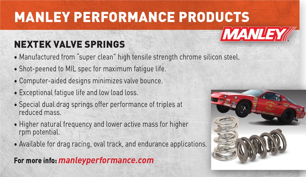
“Coatings are becoming more prevalent. We’ll use a CrN coating on the seats of titanium valves, which allows you to run steeper seat angles and increase the flow,” said Manley, noting that materials haven’t changed much over the years, but the manufacturing process has improved. “Manufacturing is really dialed in. Everyone has tightened up their acts with machining, finishes and really tight tolerances.”
“We’re doing more with the nitride coating on our Black Lightning line of stainless valves,” said Ian Levitt of QualCast, Nashville, Tennessee, noting heavy-duty applications are driving much of the development. “The demand is for diesel and natural gas engines, both stationary and off-highway applications.”
Victory 1 Performance, based in Mooresville, North Carolina, recently moved its CrN coating process in-house to put the complete titanium valve manufacturing under one roof. This move shortens turnaround time, since all valves are custom made there. However, when a valve does fail, manufacturers are quick to work with the engine builders to identify and solve any problem.
“Most of the time, customers don’t have access to failure analysis, whether metallurgical or physical,” said Derek Dahl of Victory 1 Performance. “We’ve seen just about everything when it comes to engine failures. We have had the great opportunity over the years to work with some of the most innovative and curious engine builders.”
One area where weight isn’t much of a concern is the pushrod. They keep getting as large as the block and heads will allow. Right now, the fattest is 3/4-inch in Pro Mod, but everyone is striving for the strongest, stiffest pushrod available to reduce valvetrain stress and harmonics. Trend Performance, based in Warren, Michigan, is known for producing some of the strongest pushrods on the market, yet other components that work with the pushrods were leading to failures.
“We were noticing fail points around the radius of the pushrod tip,” said Steve Rhodey, adding that the rocker adjusters on some pushrods were extremely hard. “We also noticed tooling marks on the adjusters, which were assisting the problem and causing severe galling.”
Manufacturing a tool-steel tip solved some problems, but Trend continued to see problems when open seat pressures exceeded 800 pounds. So the company developed its own line of adjusters with a material that was more compatible with Trend’s pushrods, as well as other pushrod manufacturers’ products.
One expanding market for pushrods is diesel. “The Powerstroke market has been huge for us,” said Rhodey. “There are a lot of bulletproofing kits going around, like stud kits and head gaskets. We have an upgrade to one-piece, 4130 chromoly pushrods that measure 11/32-inch diameter.” Some engine builders are asking for tool-steel valve retainers and locks, he added, due to the increased stresses on the valvetrain in boosted applications.
“We’re also seeing a new interest in tool-steel retainers,” agreed Ed Doyle of CHE Precision, Newbury Park, California. “The concern is not so much about how much they weigh, but how much more life can they give the customer. We can get these retainers close to titanium, but they will never be as light.” Recent development at his shop has focused on new products for the Gen III Hemi and new Ford 7.3-liter Godzilla V8.
At the end of the day, valvetrain technology has improved vastly in the past couple of decades because of extensive failure analysis, improved materials and exhaustive testing.
“Today you can build a 1,000-horsepower street engine,” said Manley. “It’s pretty reliable because of all the years that people broke engines and learned from it!”
Cams for Drivers
Developing and tuning an engine to suit a specific driver’s tendencies instead of building for maximum horsepower is a rather common strategy in today’s team garages. Camshaft designers are all too familiar with such requests, yet there are many nonbelievers.
“I had one guy, the only time he didn’t finish dead last was if somebody broke or crashed,” recalled Eric Bolander of Howards Cams, Oshkosh, Wisconsin. “We listened to him on how he thought he drove. Then I listened to his boss to find out how he really drove.”
Bolander’s team put together an engine package on paper that everyone thought was “totally screwed up,” but the young driver finished second the first time out with that engine setup.
“We gave him a really predictable cam that worked with his right foot,” explained Bolander. “It didn’t make him jerky, no matter what he did. It really got him to be smooth and fast.”
Over at Isky Racing Cams in Gardena, California, Nolan Jamora said he always asks about drivers’ styles. “You could say it might differ from track to track,” he noted, “but rarely will they switch styles that they grew up with. That is something we consider when grinding a cam today. One guy isn’t going to need as much coming out of a corner and he’ll want more midrange. Whereas another driver will want to run full throttle right up to the turn, jam the brakes and pull out with all the torque we can give.”
Drag racing also has its distinctive challenges.
“We have different grinds for No Prep racing,” said Jamora. “We have Pro Mod and Outlaw engine combinations that are the same but with totally different cams because of what they’re experiencing, track-wise.”
Road racing presents a more taxing task to the cam developer because there are so many more variables. Yet the key is keeping the engine strong coming out of the turns. Billy Godbold of COMP Cams in Memphis, Tennessee, said designing an engine around the driver starts first with the engine and application basics.
“Once the engine configuration and operating requirements are understood, we start to focus on the driver.” Godbold, who runs an LS-powered BMW in road-racing events, speculated on a theoretical race between himself, a “talented” driver and a “phenomenal” driver, such as Tony Stewart or Kyle Larson, and how the engine builder should think about driver abilities in the turns. The key is understanding the gears and operating rpm that each racer would utilize for the same turn—and understanding how the resulting cam specs will be “rather surprising.”
“The cam for me and a Kyle Larson would be very close to the same,” theorized Godbold. “I would be exiting the corner at a lower speed in third gear, and he might come out 15 mph faster and in second gear. If I shifted down to second, even at the lower speed, I would probably get into the throttle too fast and spin the car.
“A very good, yet not exceptionally gifted driver would come out of the same corner 10 mph faster than me but 5 mph slower than Kyle,” he continued. “They would have the throttle control to be able to control all the available torque in third gear, but not the car control to be shifting faster all the way back to second and running through the gears.”
Through a collection of charts that compare engine rpm, speed in each gear and exit speeds, Godbold put together a strong case that shows how different types of drivers can take advantage of specific cam designs that are sometimes very close together in cam strategy. Consider the following: “For the talented driver faster than me, the only reason he does not want an extra 33% wheel torque in second gear is all the shifting required takes away his concentration on the racing line. He’s faster not shifting as much as Kyle Larson but also needs the added 5% to 15% torque we can give him in the 4,000–5,500 zone with a later exhaust opening and earlier intake closing. Sure, that will take away a few percent from 7,000–8,000 rpm, but he is only there at the end of the long straights and will have better lap times and set up passes more easily with more grunt coming off the corners at lower rpm.
“For Larson or Stewart, they’re not even thinking about shifts,” continued Godbold. “They just blip the throttle as the engine approaches the redline and their right hand executes the shift almost like an involuntary response. These drivers only see that 4,000–5,500-rpm zone in the pits or during the victory lap. Giving them more in the 6,500–8,000 zone is paramount for best lap times.” —Mike Magda
Spring into Action
Increased efforts in valve-spring development have also led to more precise strategies in selecting the correct spring for a particular application. There certainly is no shortage of choices, with single, dual, triple, beehive and conical designs on the market, sometimes all from the same company with considerable testing to help validate the recommendation.
“People ask about loads, but we find that the spring mass and frequency are at least as important as the seat and open loads,” suggested Billy Godbold of COMP Cams, Memphis, Tennessee. “Valve springs and the camshaft profile are very much dancing partners. The profile leads, requiring the valve spring to follow along at low lift and then control the system at high lift. Finding the right combination requires a full systems approach.”
Jack McInnis of Erson Cams in Louisville, Kentucky, confirmed that rationale. “The primary factors when selecting valve springs in a racing engine are valve lift and rpm range along with the aggressiveness of the camshaft profile,” he said. “As engine rpm increases, so does inertia—resistance to changes in speed and direction of the valvetrain components. The valve springs play a critical role in maintaining control of those changes.”
Striving for the smallest diameter spring that will work is also proven advice, as long as the spring is strong enough to keep the lifter in contact with the camshaft.
“The larger the coil, the more amplification of harmonics,” said Chris Straub of Straub Technologies, Piney Flats, Tennessee. “Wire diameters go up in some cases or are smaller in some cases. But the actual size of the valve-spring OD has come down because of improved materials, and we’ve learned a lot as far as harmonics. Because a larger coil amplifies harmonics, we want to keep that down to a minimum.”
The topic of harmonics is a perfect segue into what many believe is the key element of selecting valve springs: the desired clearance between the spring coils at full lift. In other words, what is the measurement at full valve lift before the coils actually touch or bind together? The following sample of quotes from industry leaders shows there are both aggressive and conservative approaches to this topic.
“At maximum valve lift, most engine builders want the valve spring to be within .050- to .060-inch short of coil bind,” said McInnis of Erson Cams. “This almost coil-bound condition returns the coil spring to a uniform, stable shape on every closing cycle. If there is excessive space between the coils, the spring will be unstable.”
“Endurance valve springs have to run lower stress rates than a drag race spring, but almost all valve springs need to be run within .080-inch from bind at max lift to dampen coil surge at high speed,” explained Godbold of COMP Cams. “This can be difficult to understand, but because of the distance to bind and installed height parameters, running 0.550-inch lift camshaft with a 0.675-inch spring or 0.750-inch camshaft with a 0.900-inch spring can be almost as hard on your valvetrain as trying to run the other way around.”
“When I grew up in the shop, we were taught .070- to .100-inch clearance before coil bind,” said Straub of Straub Technologies. “Well, that’s the length of a football field these days. I mean, we’ve got people bringing the intake to almost zero—actually stacking the spring because that takes all the harmonic effect out. There’s no reverberation on the valve spring whatsoever. On the exhaust, they’re still keeping it in the .050- to .060-inch range. So, minimal coil bind is actually advantageous in some cases.” —Mike Magda
SOURCES
–
Bullet Racing Cams
bulletcams.com
Callies Performance Products
callies.com
Cam Motion
cammotion.com
CHE Precision
cheprecision.com
Clay Smith Cams
claysmithcams.com
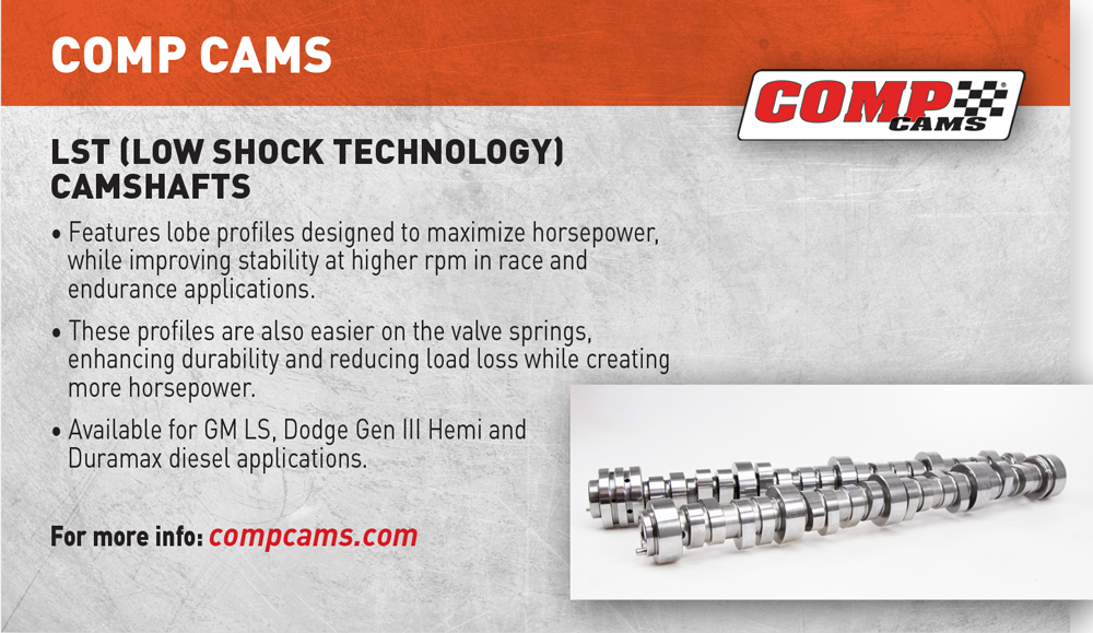
COMP Cams
compcams.com
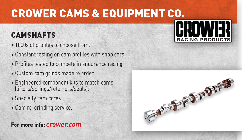
Crower Cams & Equipment Co.
crower.com
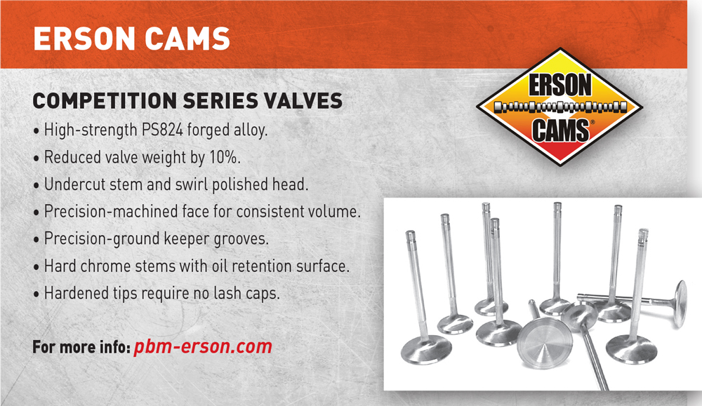
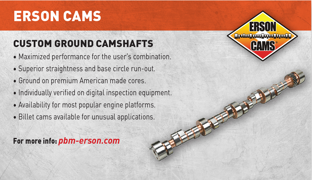
Erson Cams
pbm-erson.com
Howards Cams
howardscams.com
Isky Racing Cams
iskycams.com
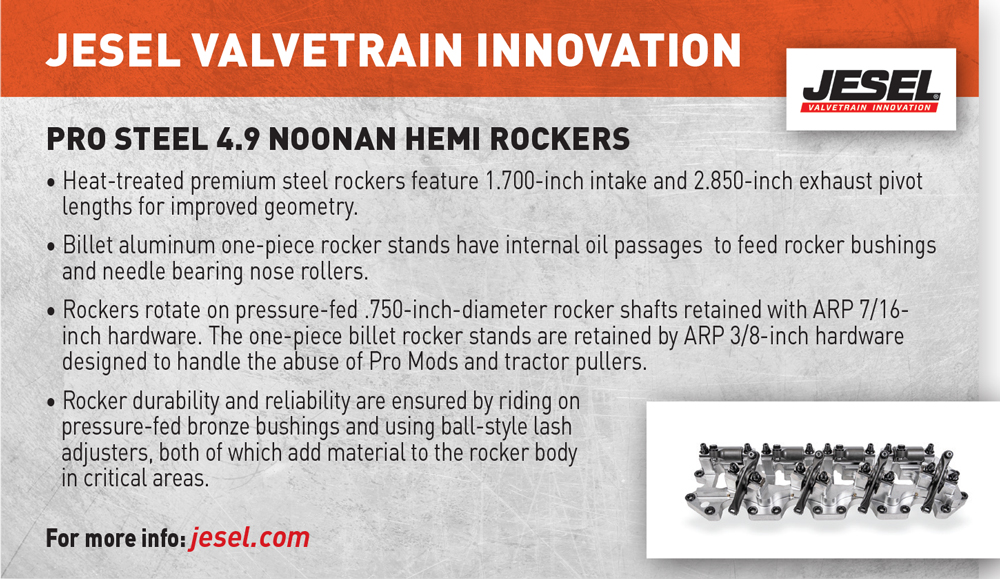
Jesel
jesel.com
Manley Performance Products
manleyperformance.com
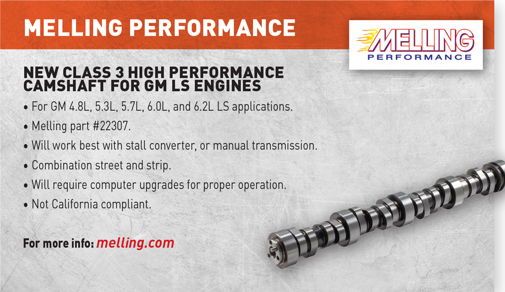
Melling Performance
melling.com
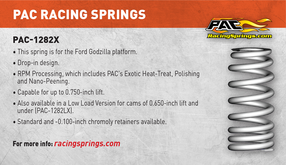
PAC Racing Springs
racingsprings.com
QualCast
qualcast.net
Straub Technologies
straubtechnologies.com
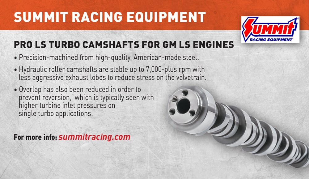
Summit Racing Equipment
summitracing.com
Trend Performance
trendperform.com
Victory 1 Performance
titaniumvalve.com