 MEMBERSHIP LOGIN
 JOIN PRI
Top-Line Tools
The tools oil system manufacturers use to produce performance lubrication systems are necessarily high-tech—except when they aren’t.
How high are the stakes when it comes to lubrication systems in race engines?
“You can break a lot of things in an engine, and it can survive, but you can’t break your oil pump. That would mean almost instantaneous self-destruction,” said John Schwarz of Aviaid, Chatsworth, California. Building a reliable oiling system is a “heavy burden of responsibility,” he said, particularly in extreme motorsports like tractor pulling. “We have a little oil pump that’s 12 inches long, 3.25 inches in diameter, and it’s basically keeping a 600 cubic inch, 6,000 horsepower, 6,500 lb.-ft. of torque diesel engine spinning a 300-pound crank at 6,500 rpm in one piece for 300 feet.”
It’s no wonder, then, that oil system manufacturers are taking advantage of the latest, state-of-the-art technology when it comes to designing and manufacturing their components. Even someone as self-described “old-school” as Verne Schumann of Schumann’s Sales and Service in Blue Grass, Iowa, admitted (with tongue in cheek) that he “survived for 40 years in machining with my fingernail test for roughness, but that doesn’t make it anymore. Now we use Mitutoyo RA technology to decipher what looks to be identical to the naked eye.”
What follows is a look at several companies making high-performance oil system components to see what kinds of cutting-edge tools they’re using, and how those tools benefit racers.
A Big Leap
“The buzzwords 10 or 15 years ago would have been finite element analysis and computational fluid dynamics, and that’s still the case. Those are still top-line tools in developing the core parts of a lubrication system,” noted Travis Rosenbarger of Boundary Racing Pumps, Royse City, Texas. Yet when designing oiling systems for racing, “there’s a lot of wear and a lot of stresses that the OEM guys don’t have to deal with. So we have to go back through and look at how the components are actually designed, and how they’re interacting, to get a component that’s going to work in the more extreme environment.”
To that end, Rosenbarger has coded some proprietary programs “that look at stress in these components and adaptively adjust the parameters that control that geometry to minimize the stress in the design.” With this kind of analysis, “you can do what a standard engineer 10 or 15 years ago would have done in a week in maybe five minutes or so and come up with a design that’s pretty well minimized in stress.” This isn’t AI at work, he explained. “It’s parameterization of these components so that, given a certain geometry, we know what stresses they’re going to incur. By putting in the specifics for whatever pump you’re doing, and then telling it to minimize the stress, it’s going to move those parameters around until it finds a minimum for that particular gear that you’re trying to design. That is a big leap. Where it used to take me about a week to make a design for a new gear set, I can now competently create a gear in maybe an hour, hour and
a half.”
Rosenbarger has also tied this design step into the manufacturing process. “I parameterize the model to minimize the stress, which gives me the geometry. Then the geometry itself is linked to CNC programming machining templates that I can copy on top of, so in that hour and a half or two hour window, I can come out with G code that’s ready to go to the machines to actually produce the first prototype part and see how it’s done.”
Technological advances are also helping on the quality control side of the business, he said. “There’s a wide variety of equipment from different manufacturers where you can give the machine the critical inspection components, slide that gear in front of it, hit go, and it’ll do visual recognition of the component. Then it knows how to go in and probe the exact points that you want it to, to tell you if the part is in compliance.”
At Boundary, “every single gear now gets a CMM scan,” Rosenbarger added. “Every inner and outer rotor that goes on a set gets a CMM scan, along with some other hand inspection techniques. That also would not have been possible 10 or 15 years ago, not on any kind of budget the automotive industry would recognize.”
That’s largely because the tools have become “very cost effective,” Rosenbarger said. “In the old days, you had software that you would have to program, and a lot of times, the programmer for that software would carry a six-figure salary. Then the software itself was $40,000. And then you have the hardware that would be $400,000 or $500,000. Today, all of that has culminated into more compact systems that cost well south of $100,000 that ordinary users can interact with. That’s been really impactful to our quality.”
More Accurate Design Environment
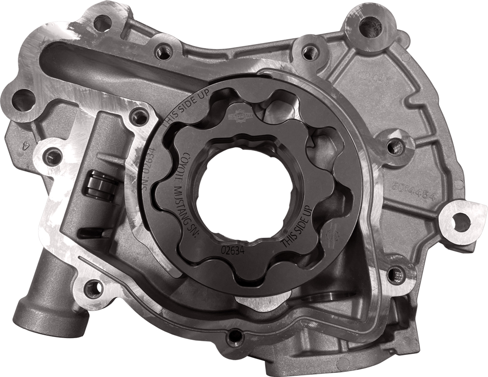
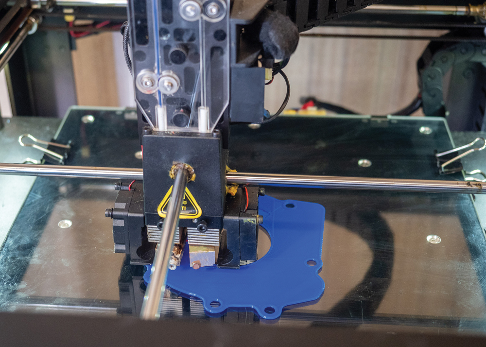
In 2018, Melling Tool Company of Jackson, Michigan, began using fused deposition modeling 3D printing “to allow our engineering department to 3D print products and components for development and static prototype evaluation on engines and vehicles to ensure proper design fit-up, envelope clearances, and overall feasibility before permanent tooling is produced,” said Travis Stevens.
Prior to having 3D printing capabilities, Melling would order stereolithography or selective laser sintering parts from outside service providers, “resulting in multiple weeks for delivery timing and costs of hundreds to thousands of dollars,” Stevens explained. “Now we can make a 3D-printed component within hours, review the components on the engine, make any needed changes, and re-print the component for further evaluation.”
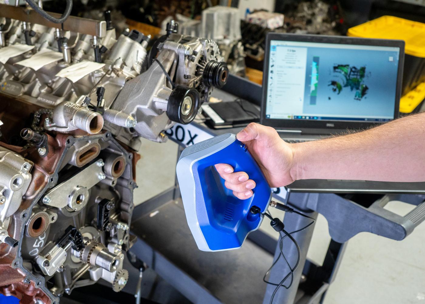
Also in 2018, Melling started using 3D portable scanning equipment “for reverse engineering and 3D CAD model to physical product overlay validation,” Stevens continued. “3D scanning of engine components and vehicle physical attributes has allowed for a more accurate 3D design environment for our engineers to understand existing components on the engine and design in the proper packaging clearances prior to making any physical components. Melling engineers can make sure the designed oil system components do not have any spatial interference with other nearby components and assemblies on the engine or vehicle. 3D scanning has also allowed for casting validation between the physical castings and the intended 3D product design. Castings are scanned and compared against the 3D CAD casting models to make sure that the castings being supplied to Melling are being manufactured within the needed design requirements.”
An added benefit of Melling’s 3D printing is convenience, according to Stevens. “3D printing of various oil system components has allowed us to make multiple prototype copies of the same component that could be used in different manufacturing disciplines at the same time,” he said. “A 3D printed oil pump housing, for example, could be printed multiple times and used for product design validation, tooling and fixture development, a visual aid for various meetings, and manufacturing processes development. Prior to 3D printing capabilities, only one prototype would have been ordered due to timing and cost constraints, and this one prototype would then have to be shared amongst all departments.”
Extremely Fast and Accurate
At Moroso Performance Products of Guilford, Connecticut, Engineering and R&D Manager Frank Kokai and Operations Manager Gary Burkle walked us through some of the equipment Moroso uses on the R&D and manufacturing sides of the house.
When R&D gets a request to build a new oil pan, for example, “we’ve invested in a Hexagon portable CMM, which allows us to verify dimensions on blocks for pan rail locations, bolt hole locations, main caps, and other features, before we even get to the design stage,” said Kokai. “Then we can take that information and import it directly into our Creo CAD design software.”
Moroso used the Hexagon CMM in the creation of a series of V-Band drive pumps for ProCharger applications, Kokai said. “We worked with the manufacturers and used the Hexagon arm to gather the data we needed to design the pumps to bolt directly to the ProCharger system. Then we worked with chassis and engine builders to gather data and import that into our software to make the system work seamlessly together.”
When looking at manufacturing, “the CNC machines haven’t changed much, but the software has,” Kokai said. “It is constantly evolving. The software we use to program, Mastercam, has advanced tool paths that allow us to machine materials quicker, more efficiently, and more accurately.”
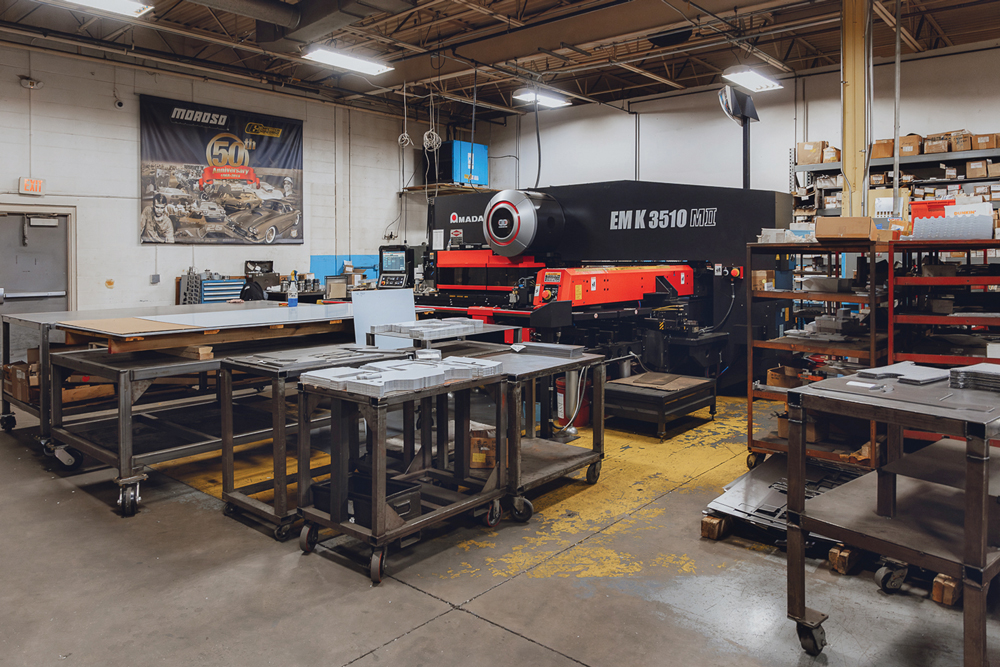
“On the sheetmetal side, over the last five years we have updated all of our turret equipment,” Burkle said. “We have invested in two Amada EMK servo-driven turret punches that allow us not only to punch and profile a part, but we can also form features in the machine.”
“There are 58 stations with live, indexable heads,” Kokai added, “with tooling that allows us to punch and form features into the sheet metal in the turret without having to take it to a secondary operation. That’s something you couldn’t always do with the older hydraulic driven machines. These are also extremely energy efficient compared to the old hydraulic machines. Plus, they’re extremely fast and accurate.”
Advanced technology, combined with the investment in new machines, has allowed Moroso to take a concept from the design stage through prototype and bring it to market faster than ever before.
“The communication that happens from engineering to manufacturing is almost seamless in today’s world,” Burkle said. “That’s a big change. We can update the design in Creo, and within a day, the floor is updated completely with new prints and machine files. You can revise a singular product, stop its production for the day, and have the revised product in production within the same day.”
The Benefit is Speed
ARE Dry Sump Systems of Loomis, California, has been “designing and manufacturing dry sump components for racing engines since 1978,” said Gary Armstrong. “We start with a ‘blank sheet of paper’ design and make all our casting tooling, patterns, fixtures, etc. in-house.” Prior to the widespread adaptation of CNC machining, “precision surfacing and drilling fixtures were used on the castings. For many of the older, lower volume dry sumps they still are.” But the company also has several Haas three- and four-axis CNC machines to manufacture its newer designs, as well as Autodesk Fusion 360 or Solidworks computer software. “We also make use of modern time benefits such as CFD, CAD/CAM, as well as input from the factories, pro racing teams, and engine builders.”
When we asked Armstrong for an example of a dry sump system he was able to create or improve by using these high-tech tools, he said, “the only real benefit is in speed of production. Modern manufacturing does not make anyone any smarter.”
Necessary Precision
When Aviad started building oil pumps in 1968, “it was all done on tracer equipment—tracer mills, tracer lathes,” Schwarz explained. By the time he joined the company in 1998, manufacturing had been converted to CNC machines, though initially the company used an earlier generation, numerical control (NC) machine that was fed cutting instructions via tape.
The precision that current CNC machining technology brings to oil pump manufacturing has been a benefit as preferences are switching from petroleum-based to synthetic oils, and those oils have gotten lighter, Schwarz said. “When you’re looking at thinner and thinner oils, oils with smaller and smaller molecules, you’re talking about pumping water, not oil, anymore. So you have to be able to grab hold of that oil and move it to where it has to get to. That’s where the technology has helped, because with the CNC manufacturing processes that we have now, it’s much easier to maintain the gear-to-housing clearance numbers.”
Aviaid contracts most of its CNC machining to companies with five-axis machines “so that we can get a single setup. That’s the whole key to multi-axis machining,” Schwarz said. “When you’re machining a housing, you’re doing it on so many planes, if you were doing it on a regular CNC mill, you’d be doing three or four setups with every part. That gets a little tedious. So the five axis-stuff really helps that part of the business.”
Credit, too, goes to the expertise of the machine’s operator, Schwarz added. “The trick is not only designing and programming the part, but then there’s building the fixturing, and the tooling, and getting it all set up and running properly so you get the desired results.”
Yet the five-axis machines—and their operators—can have weaknesses. Schwarz cited one experience he had where a night-shift operator failed to take into account the thermal dynamics of ambient temperature change compared to the daytime, and part-to-part tolerances slipped to unacceptable levels.
These technologies can “really sound good until you do the deep dive, and then you have to understand the strengths and weaknesses of each process,” Schwarz said. “The trick in making the same part today that we made 50 years ago is really understanding how the manufacturing process has evolved. Each new step engenders different issues.”
Self-Taught
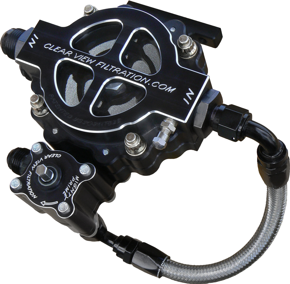
To manufacture his see-through oil filters and other components, Mike Cofini of Clear View Filtration in Spokane, Washington, utilizes six Haas CNC machines. Somewhat surprisingly, he said he’s “never been trained in CNC machining,” even though he and his partner, Jessie Juel, have written “every single program ourselves. We’ve never had anybody come in and teach us anything. For an old-school guy like me [Cofini spent 30 years building race engines before starting his filter company], it’s been about the Internet and how we can research things.
“Technology is moving forward at the same speed our cars are,” he said. “The information is out there. People just need to research it.”
Internet research and the design programs he’s found there were key in the development of Cofini’s latest product, a priming system that incorporates a small oil pump in a stand-alone unit that can be easily mounted to a Clear View filter. The priming unit will be incorporated in the base of the filter and can “make 70 pounds of pressure on a big block Chevy with just a 12-volt cordless drill.” Cofini said he expected to spend a month developing the pump, “and we actually spent a week and a half. Honestly, without the technology of that newest program [which he sourced from an engineer in the UK who was familiar with his filters], we probably could not have accomplished that on our own.”
Cofini recently had his Haas machines tested to make sure they were still within factory spec for accuracy, and he has also upgraded the cutters. “There are some better cutters that have just come out, and we’re getting better tolerances because of the upgrade in cutter technology.”
Build it Ourselves
Innovation has marked Verne Schumann’s long career in performance lubrication systems, from his “paddle wheel” oil pumps and oil pressure warning lights to his latest new product, a 120% external bypass system, for street, strip, and race applications, that re-engineers the factory cup valve in small block Chevrolet engines. Schumann has applied that same level of innovation to the machinery he uses in producing and quality-checking his oil system products.
“The trouble with oil pump manufacturing is you can’t just pick up the phone, order 10 machines, and be in business next week,” he said. “All the equipment that we use in-house to check flow, pressure, volumetric, feet per second, we have to build ourselves.”
Schumann contracts out what he called the “heavy manufacturing that we have done to our specification, such as foundry and three- and five-axis machining. When those parts come in to us, we do the final machining.”
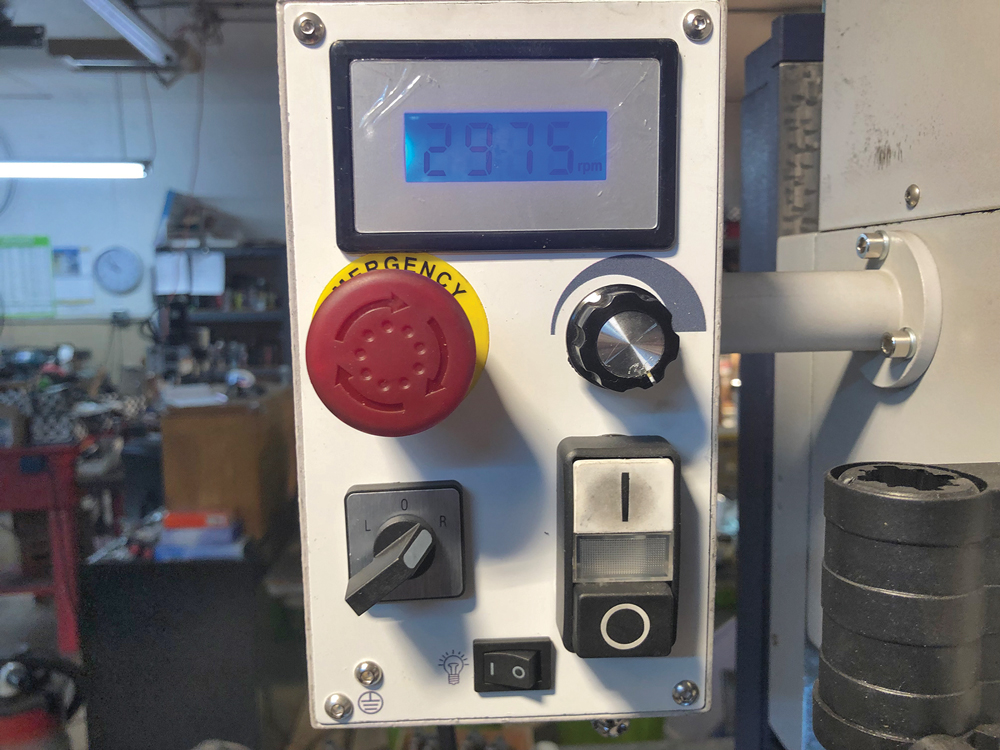
One of the newest additions to his shop is a milling machine “that we had built especially for our use,” he said. “It took a year to get it the way I want it.” The machine has electronic rpm control “because in some cases, when you’re doing a precision bore, the same speed from top to bottom through the bore is not the answer. You want to vary it as you go deeper and increase the rpm to get the chips to come out. Once a chip doesn’t come out, it grinds itself up and ruins the surface finish.”
This machine also had an electronic readout that “shows the vertical feet of the milling,” Schumann said. With most milling machines, “the depth of the plunge is controlled by go and no-go gauges or a mechanical micrometer you have to check and recheck. With this machine, I can see on a digital readout how much material we’re removing in real time.”
Schumann’s inquisitive mind is open to the benefits of the latest technology unless that latest tech doesn’t serve his purpose. His custom milling machine, along with a Fowler TH550 electronic hardness tester, SP profilometer, and Mitutoyo surface roughness tester, share space with the diamond paper used to hand-lap valve or surface plates. “Hand lapping is still the most accurate way to get the proper surface finish on a flat part,” he said, and his preferred procedure is accomplished by triangulation lapping. “You do three strokes, rotate the part a third, do three strokes, rotate the part a third, and so on. We have four different levels of lapping depending upon the racer’s oil usage: aggressive lapping for 70 weight, very fine structured lapping for 0 weight, and points in between.”
There are lapping machines, and he has owned them, but they lap in only one direction. “Then the oil follows the direction of the lapping grid and doesn’t stay in place long enough to separate parts.” It is possible to rotate the part in a lapping machine, Schumann explained, but it is far more time consuming than in the hand-lapping process.
“We try to go more and more to the newest technology if we can, but still, in some cases, the old stuff is still the only answer.”
SOURCES
ARE Dry Sump Systems
drysump.com
Aviaid
aviaid.com
Boundary Racing Pumps
boundarypumps.com
Clear View Filtration
clearviewfiltration.com
Melling
melling.com
Moroso
moroso.com
Schumann’s Sales & Service
schumannssalesandservice.com